
Wiring harnesses are divided into high-voltage and low-voltage harnesses. Gasoline-powered vehicles only have low-voltage harnesses, powered by the battery, with power distribution handled by a fuse box. High-voltage harnesses are more commonly found in new energy vehicles.
Let's briefly discuss the composition of a wiring harness. Wiring harnesses are actually common in daily life. The simplest USB cable and the network cable used for gaming are examples of simple wiring harnesses.
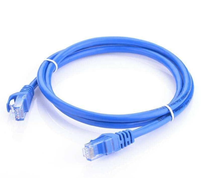
Take a simple network cable as an example. First, structurally, the components separated from a network cable are as follows: plastic (connector), terminal, cable, and sheath!
Plastic component, also known as a connector or sheath, commonly called the "head"! Its main material is plastic, which has good insulation properties. Connectors, crimp terminals, and drain plugs are collectively called wire harness connectors. Wire harness connectors act as a "bridge" in the vehicle's electrical architecture. Since hundreds of connectors are used in a vehicle, wire harness connectors are often distinguished by shape, number of holes, and special colors to prevent assembly errors. A connector is shown in the image below.
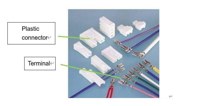
Wire harness crimp terminals, commonly called terminals, use plastic as a carrier to achieve conductivity between cables and electrical components. Terminals are generally made of copper, and the contact surfaces are often zinc- or tin-plated to enhance conductivity. For vehicle safety components such as airbags, silver-plated terminals are used. For other parts requiring high contact resistance and corrosion resistance, gold-plated materials can be used for the terminal contact surfaces. The image below shows a terminal structure diagram.
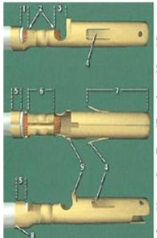
As a complex structure, terminals must not only meet geometric dimensional requirements but are also typically inspected visually, using cross-sectional analysis to check the rationality and correctness of the crimping between the terminal and the cable. After crimping, tests are needed to verify the reliability of the terminal's function and structural performance. Common tests include tensile tests and contact resistance tests.
Terminal tensile testing checks the tightness of the connection between the metal terminal and the wire core, using a universal tensile testing machine. The test is repeated until the wire core detaches from the terminal, and the data on the tensile testing machine's instrument panel is recorded.
Contact resistance is the resistance value of the contact area between the terminal and the wire core. Generally, contact resistance should be less than 30mΩ, although standards vary between companies.
The sheathing of a wire harness refers to what is wrapped around the outside of the cable. This includes tape, corrugated tubing, PVC pipe, rubber sheath, fiberglass tubing, etc
| Type | Material | Key Features | Main Use | Notes |
| Tape (General) | Various (Cloth, PVC, Sponge) | Versatile: bundles, protects, insulates. | General wire harness wrapping. | Choose type based on environment. |
| Cloth Tape | PE + Fiber Composite | Strong, durable, oil/water resistant, easy tear. | Common in automotive harnesses. | Robust all-rounder. |
| PVC Tape | PVC | Good insulation & waterproofing. | Repair and insulation of stripped wires. | Avoid high temps (>80°C). |
| Sponge Tape | PE Foam + Adhesive | Shock absorption, cushioning. | Door harnesses; protects connectors. | For specific cushioning, not general wrap. |
| Rubber Sleeve | Rubber | Flexible, abrasion resistant. | Wire pass-through points & moving parts (doors, hinges). | Pre-made sleeve, not a tape. |
Cables are the main structural component of a wire harness, consisting of a copper core and an outer insulation layer. Cables are available in various specifications based on the cross-sectional area of the conductor. The image below shows four conductors with different cross-sectional areas, from left to right: 0.5 mm², 0.75 mm², 1.0 mm², and 0.35 mm².
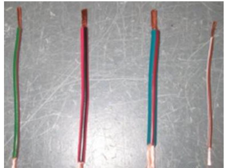
Different wire harness specifications have different impedances and maximum current capacities. The maximum current allowed to pass through conductors of the same diameter also varies at different temperatures. To avoid excessive heating of the conductor, the current density should be checked. The formula is (I - current, A - conductor cross-sectional area):
S = I/A A list of common conductor diameters and their current capacities is as follows:
| Conductor Cross-Sectional Area (mm²) | Continuous Allowable Current at 30℃ | Continuous Allowable Current at 50℃ | Allowable Current Density |
| 0.35 | 8 | 6.5 | 10 |
| 0.5 | 11 | 7.8 | 10 |
| 0.75 | 15 | 10.6 | 10 |
| 1.0 | 19 | 13.5 | 10 |
| 1.5 | 24 | 17 | 10 |
| 2.5 | 32 | 22.7 | 10 |
| 6.0 | 54 | 38.3 | 6 |
| 10.0 | 73 | 51.8 | 6 |
| 25 | 129 | 91.6 | 4 |